
H
1(2)
=
l
0
sin
α
1(2)
+
l
E
;
L
1(2)
=
l
0
cos
α
1(2)
+
l
E
;
l
sw1(2)
=
q
(
H
+
h
1(2)
)
2
+ (
L
1(2)
−
l
E
)
2
;
δ
1(2)
=
l
sw1(2)
−
l
sw1(2)
— is the shock absorber length change;
x
1
=
l
0
cos(
α
1
−
ϑ
) +
l
E
cos
ϑ
+
h
0
sin
ϑ
;
x
2
= cos
γ
2
(
l
0
cos(
α
2
−
ϑ
2
) +
l
E
cos
ϑ
2
+
h
0
sin
ϑ
2
);
β
1(2)
= arcsin
L
1
−
l
E
l
sw1(2)
.
(6)
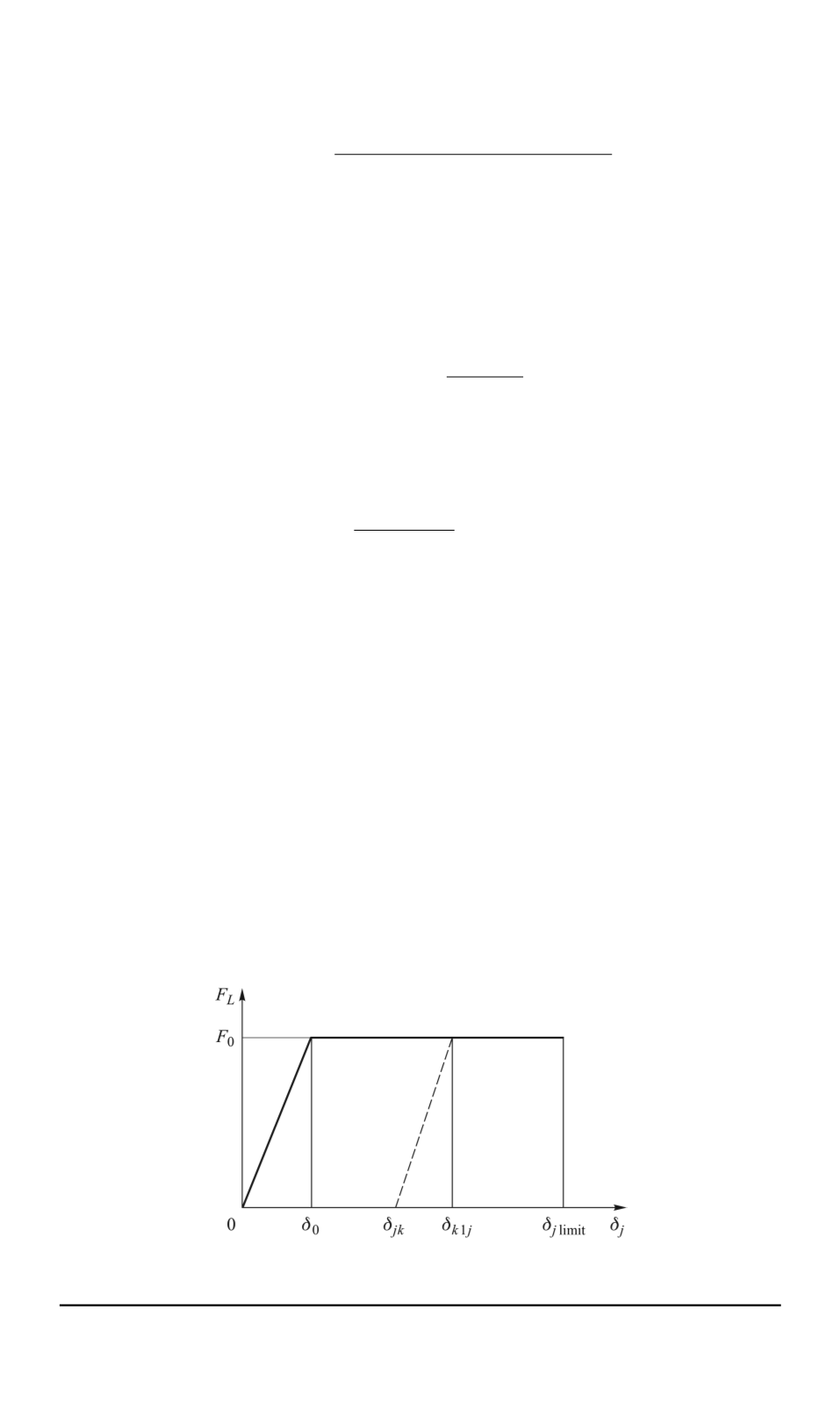
As it is shown in Fig. 4, we can find the shock absorber force by the
known
δ
1
.
F
L
1(2)
(
δ
) =
0
, δ
1(2)
≤
δ
jk
;
F
0
δ
1(2)
−
δ
k
1
δ
0
, δ
jk
< δ
1(2)
< δ
k
1(2)
;
F
0
, δ
1(2)
≥
δ
k
1(2)
,
(7)
here
δ
0
— is an initial value of the flexible deformation region of the shock
absorber;
δ
k
1
j
— is a current value of the flexible deformation region of
the shock absorber;
δ
jk
— is an initial value of the deformation during
j
-th
contact between the leg and the terrain,
F
0
— is a force during the shock
absorber destruction.
Let us formulate the force equilibrium equations in the point
А
of the
first (second) leg along the
OX
axis and the
OY
axis. After doing the
transformations, we shall obtain the formula for calculating a soil reaction
on the leg:
F
1(2)
=
F
L
1(2)
cos(
α
1(2)
+
β
1(2)
)
/
cos(
α
1(2)
+
μ
1(2)
−
ϑ
)
,
(8)
here
μ
1(2)
— is a friction coefficient on the first (second) leg.
Fig. 4. Shock absorber force characteristics
30 ISSN 0236-3941. HERALD of the BMSTU. Series “Mechanical Engineering”. 2014. No. 1


