
This makes it possible to estimate the full loads on the spacecraft landing
gear.
Let us formulate a mathematical model of the spacecraft motion at the
last stage of landing on a small celestial body.
The main assumptions are the following ones:
a) we consider a longitudinal motion of a spacecraft with three legs;
b) aerodynamic forces are neglected;
c) gravitational acceleration is constant;
d) friction in the joints of the legs is neglected;
e) a spacecraft landing site on a celestial body is considered to be rigid.
During the development of a mathematical model of the spacecraft
motion, the following coordinate systems are used:
1) the surface coordinate system (SCS)
X, Y, Z
, associated with the
celestial body surface (
X
and
Z
axes lie in the plane of the landing surface,
X
axis lies in the plane of the first leg);
2) the spacecraft fixed coordinate system (FCS)
X
c
Y
c
Z
c
, directed along
the longitudinal axis of the spacecraft,
X
c
axis is perpendicular to
Y
c
axis
and lies in the plane
XY
of the SCS,
Z
c
completes the right hand triple of
the coordinate system;
3) the gravitational coordinate system (GCS)
X
g
Y
g
Z
g
(
Y
g
axis is
directed along the line of the gravitation force action,
X
g
axis is perpendicular
to
Y
g
axis and lies in the plane
XY
of the SCS).
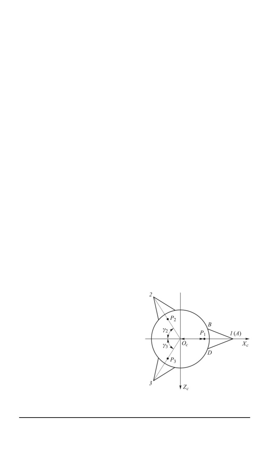
Fig. 1 shows a top view of the spacecraft. Numbers
1
,
2
,
3
refer to
contact points between the legs and a celestial body; points
P
1
, P
2
, P
3
refer
to locations of the thrusters. Angles
γ
2
, γ
3
denote a rotation of the second
and third legs relative to the axis
O
c
X
c
; points
B
and
D
refer to the struts
attachment.
Fig. 1. Top view of the spacecraft with
three legs
The dimensions of all the legs
are identical. Fig. 2 shows the main
dimensions of the first leg:
l
0
(
AE
)
— is
a projection of the legs
AB
,
AD
on the
plane
X
c
Y
c
;
l
sw
(
АС
)
— is the length
of a rod with a shock absorber;
l
E
—
is the distance from the center of mass
(CM) of the spacecraft to the point
Е
along the
O
c
X
c
axis;
h
0
, h
1
— are the
distances from the spacecraft CM to
the attachment points of the strut and
the shock absorber, respectively;
H
—
are the distances from the spacecraft
center of mass to the point
А
along the
ISSN 0236-3941. HERALD of the BMSTU. Series “Mechanical Engineering”. 2014. No. 1 27


