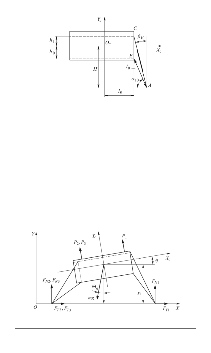

Fig. 2. Main dimensions of the shock absorber and the rod attachment to the
spacecraft
O
c
X
c
axis;
α
0
— is the strut inclination angle relative to the line, which is
parallel to the
O
c
X
c
axis [7].
Fig. 3 shows the main forces acting on the spacecraft during landing.
P
1
, P
2
, P
3
— are the thrust forces;
mg
— is the gravitational force;
F
N
1
,
F
N
2
,
F
N
3
— are the projections of the terrain reaction in the direction of
the
OY
axis of the SCS;
F
T
1
,
F
T
2
X
,
F
T
3
X
— are the friction forces of the
three legs along the
OX
axis of the SCS.
The following designations are also present in the figure:
ϑ
— is the
spacecraft inclination angle relative to the
OX
axis;
Θ
g
— is the angle
between the gravitational vertical and the
OY
axis of the SCS.
Differential equations describing the longitudinal motion of the spacecraft
during landing on the surface of a celestial body along the axes of the SCS
of the spacecraft can be defined in the following way [8]:
Fig. 3. Forces acting on the spacecraft during landing
28 ISSN 0236-3941. HERALD of the BMSTU. Series “Mechanical Engineering”. 2014. No. 1


