


 17 / 21

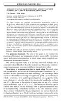
Fig. 5. Spatial distribution of pressure (
a
) and temperature (
b
) at the moment
t
= 9
.
1
ms (Experiment 4):
1
— shock-compressed test (driven) gas behind the reflected shock wave;
2
— reflected
shock wave front;
3
— area of the initial shock-compressed test (driven) gas;
4
— contact
boundary front;
5
— space occupied by the rarefaction wave in driver gas
the most significant peculiarity of the interaction of a shock wave with
a solid barrier is the shock wave amplification after its reflection from
the barrier [10]. It is convenient to characterize the process of the shock
wave reflection by the relative amplification coefficient:
K
=
Δ
p
3
Δ
p
2
, where
Δ
p
3
=
p
3
−
p
1
is the excessive pressure in the reflected shock wave,
Δ
p
2
=
p
2
−
p
1
is the excessive pressure in the incident wave.
From graphic curves given in Fig. 3, it follows that the shock wave
collision with the solid barrier results in the appreciable amplification of
the reflected shock wave: the amplification coefficient
K
≈
6
(for air the
maximum value of amplification coefficient is
K
= 8)
. The amplitude
value of the reflected shock wave
Z
≈
24
, the temperature and pressure
at the right computed boundary increase to
T
≈
1
.
2
кK,
p
≈
3
.
5
atm.
By this moment, the fan-shaped flow of rarefaction waves has already
reflected from the left computed boundary and moved more than half into
the computed zone. Along with it, the temperature and pressure at the left
boundary have dropped to
T
≈
0
.
2
кK,
p
≈
7
atm.
Then, mostly at the right computed boundary, we can observe the flow
structure (Fig. 6) corresponding to the phase of complex interaction of the
shock wave, contact discontinuity, and rarefaction wave, which expands
approximately for
10
.
3
6
t
6
10
.
3+
L
HP c
+
L
LP c
c
1
≈
35
ms. The reflected
shock wave interacts only with the contact discontinuity that moves towards
it at the initial stage of the phase of flowing in the shock tube in the vicinity
of the right computed boundary.
In this case there can be two options of the interaction: a) if the shock
wave interacting with the contact discontinuity expands from the denser
ISSN 0236-3941. HERALD of the BMSTU. Series “Mechanical Engineering”. 2014. No. 1 19