


 16 / 21

While developing an approximate one-dimensional model, a scheme
of the computed area was used, as shown in Fig. 2. On the left side of
the computed area there is a shock tube end wall for which a boundary
condition was set, that of gas medium “non-leaking” through a solid
barrier. On the right side of the integration field, the boundary condition
of “non-leaking” was also stated. Thus, during the computation, it was
approximately assumed that on the left side, the shock tube is limited
by a solid wall (actually in this shock tube (at the Institute of Applied
Mechanics, RAS, see Fig. 2), there is a Laval nozzle).
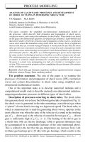
The resulting initial structure of the gas flow after the rupture of the
diaphragm is shown in Fig. 4 and described in the notes. This structure of
gas flow corresponds to the phase of wave system autonomic distribution
in the space and extends for a time interval
0
6
t
6
0
.
85
ms. As known
[10], the shock wave intensity is accepted to be characterized with a
dimensionless parameter called a shock wave amplitude:
Z
=
p
2
−
p
1
ρ
1
c
2
1
.
The levels of temperature and pressure values behind the shock wave front
at this stage are specified by
T
≈
0
.
7
кK,
p
≈
0
.
7
atm. In the vicinity of
the computed area boundaries, the gas is not disturbed and corresponds to
the initial conditions (right boundary —
T
= 298
.
15
K,
p
= 19
atm; left
boundary —
T
= 298
.
15
K,
p
= 0
.
1
atm). The following flow structure is
observed for the time interval
0
.
85
6
t
6
10
.
3
ms and is up to the phase
of the initial interaction of shok waves and rarefaction waves with a solid
barrier.
The result of shock wave reflection from the solid barrier that is located
on the right of the area of integration is shown in Fig. 5. It is known that
Fig. 4. Spatial distribution of pressure (
a
) and temperature (
b
) at the moment
t
= 3
.
4
ms after the rupture of the diaphragm (Experiment 4):
1
— unperturbed test (driven) gas;
2
— shock wave front;
3
— area of shock-compressed
test (driven) gas;
4
— contact boundary front;
5
— space occupied by the rarefaction wave
in the test (driven) gas;
6
— space corresponding to the initial state of the driver gas in
the high pressure chamber
18 ISSN 0236-3941. HERALD of the BMSTU. Series “Mechanical Engineering”. 2014. No. 1