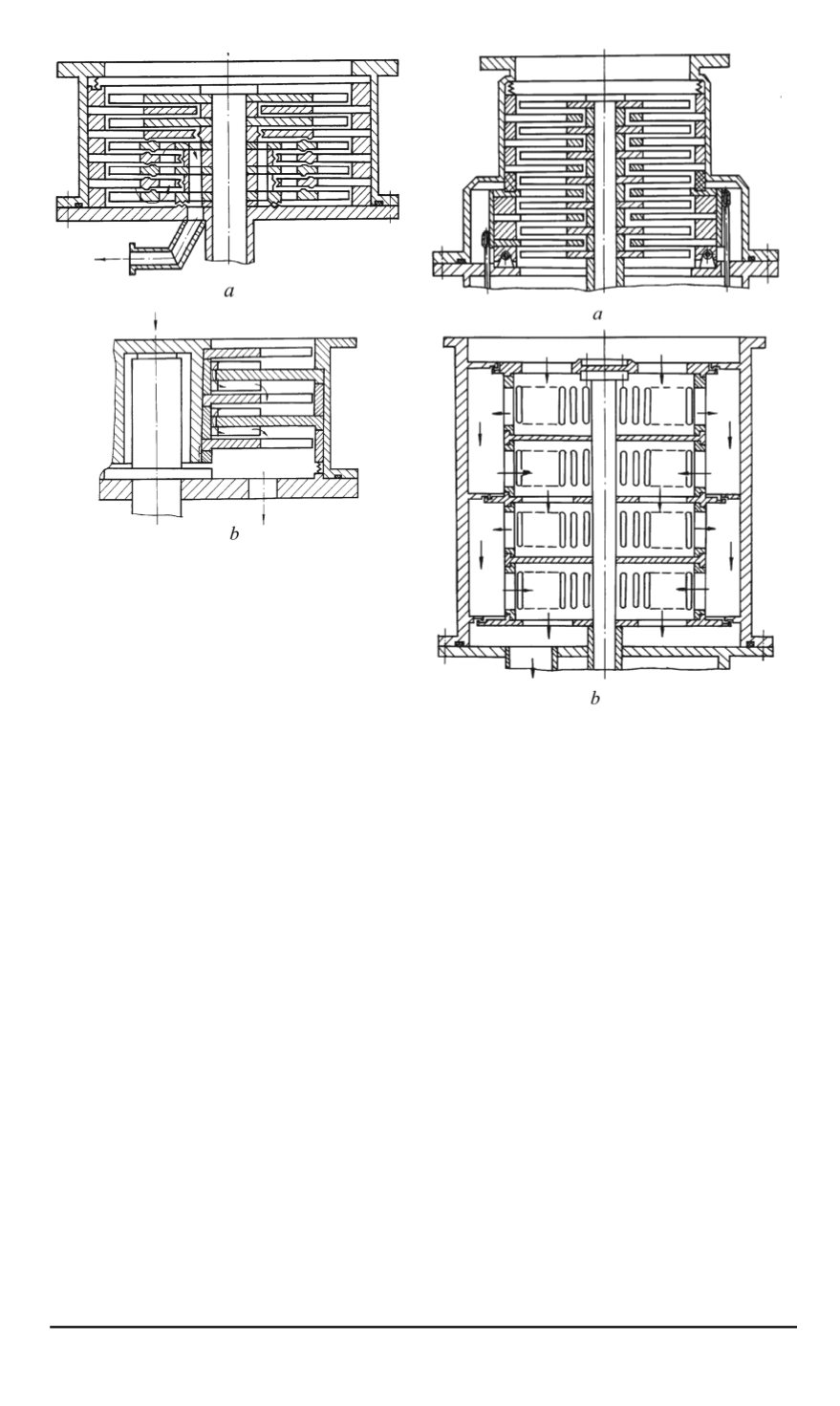

Fig. 2. TMP structural scheme with gas
reversing (
a
) and frontal radial blade
on stator wheels (
b
)
Fig. 3. HVMP design arrangements with
adsorption pumps on the pressure side
(
a
) and axial and radial gas flow in the
rotor (
b
)
Another perspective trend of HVMP improvement consists of combining
TVP elements with other types of high-vacuum pumps based on different
operating principles in the flow channel.
A TMP design arrangement (Fig. 3,
a)
was suggested with an adsorbent
located in special cavities of the exit stator wheels. This enables additional
gas evacuation in these wheels. To increase the gas absorption efficiency,
these wheels (located on the pressure side) are cooled up to 80. . . 100 K
with liquid nitrogen fed into a special cooling jacket in a special vacuum
chamber. This flow channel arrangement eliminates the need to use oil fore
pumps for the initial vacuum when putting the pump into operation with
the help of the atmospheric pressure, as this function will be performed by
an adsorbent. Moreover, the adsorbent regeneration will be realized without
stopping the TMP and disengaging it from the pumping system.
It is known that TMP should not be used for gas media containing solid
macro particles without special protection since it results in the degradation
of pump parameters.
ISSN 0236-3941. HERALD of the BMSTU. Series Mechanical Engineering. 2014. No. 5
5


