


 7 / 10

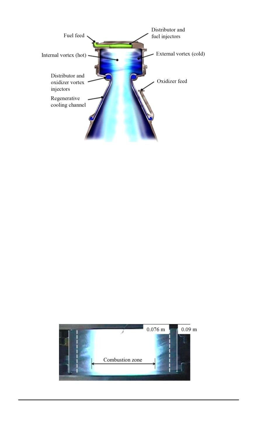
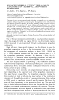
Fig. 4. Rocket engine with vortex cooling [10]
(calculated with the help of CEA-2000 software), for СН
4
+ О
2
— 98%,
for CO + O
2
— 86%. Furthermore, the temperature of the chamber wall
increased by 2. . . 8
◦
С compared to the initial temperature for the H
2
+ O
2
rocket engine.
The potential of this chamber arrangement method is evident; however,
the experimental data in [10] are insufficient to draw conclusions about
the thermal efficiency of this cooling method. Duration of LTRE hot tests
is not enough to determine both the combustion efficiency and a specific
impulse. It does not provide adequate information on the stationary thermal
state of the combustion chamber wall as well.
The influence of the coolant injection angle on the film cooling
efficiency was studied in [11–14] (Fig. 6,
b
). The results of the experiments
indicate that the increase of the coolant injection angle results in decreasing
the cooling efficiency, with its dropping to the minimum during the radial
injection. This can be attributed to the film being washed out by the main
flow because of different flow directions and rates.
Fig. 5. Image of the combustion zone limited by the internal vortex [10]
86 ISSN 0236-3941. HERALD of the BMSTU. Series “Mechanical Engineering”. 2014. No. 1