


 6 / 10

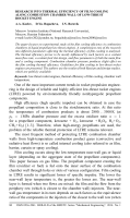
Fig. 3. Influence of coolant
mass flow-rate on film
cooling efficiency [9]:
1, 3
and
5
— nitrogen,
m
f
= 6
, 11 and 15%;
2, 4
and
6
— kerosene,
m
f
= 9
,
5 and 14% respectively
pressure
p
k
= 2
MPa and the constant mixture ratio
K
m
= 3
.
2
. The
value of the coolant relative mass flow-rate
˙
m
f
varied from 0.05 to 0.15.
The results prove that the higher the coolant relative mass flow-rate is,
the higher the film cooling efficiency becomes. With the distance from
the coolant injection point increasing, the cooling efficiency gradually
decreases (Fig. 3)
Special attention should be paid to [10]. This paper considers the
thermal state of the RE combustion chamber walls working on gaseous
СН
4
+ О
2
, H
2
+ O
2
, and CO + O
2
propellant combination. Such engines
feature a new cooling method, so called “vortex cooling”. The method is
essentially the following: the whole amount of oxidizer used as a coolant is
fed into the combustion chamber not via a mixing unit but through cyclonic
ports located in the cylindrical axisymmetric segment of the chamber. This
cyclic injection results in forming a coolant vortex along the combustion
chamber wall, which restrains the combustion within the chamber core
unit, thus reducing the heat transfer to the wall surfaces. In its turn, the fuel
is injected via a mixing unit and is entrapped into the oxidant vortex flow
in the chamber, forming an internal vortex where the combustion occurs.
The general layout of this engine is shown in Fig. 4.
A transparent acrylic segment of the combustion chamber was used
to visualize the flow for this cooling method during the hot starts. Fig. 5
presents an image of the cylindrical combustion chamber in the process
of H
2
+ O
2
combustion with
K
m
= 6
mixing ratio and
p
k
≈
0
.
9186
MPa
chamber pressure. Information for the scale: the external diameter of the
chamber acrylic segment is 0.09 m.
According to Fig. 5 the combustion zone is restricted within the
chamber internal area, a ring of cold gas separates the wall inner surface
from the combustion zone.
A series of two-second hot starts was performed. The test results show a
high efficiency of engines performance. For instance, for the H
2
+ O
2
rocket
engine specific impulse constituted 97% of the one theoretically possible
ISSN 0236-3941. HERALD of the BMSTU. Series “Mechanical Engineering”. 2014. No. 1 85