


 3 / 10

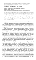
Fig. 1. Positioning configuration of the coolant supply slot [6]
where
ρ
2
and
ρ
∞
are densities of the coolant and the main flow;
u
2
and
u
∞
are feed velocities of the coolant and the main flow;
2) pressure in the combustion chamber;
3) design and position of the slot.
The study results show that the greater
M
is, the higher the film
cooling efficiency becomes, while pressure influences the cooling efficiency
insignificantly.
To study the influence of the slot position on the cooling efficiency, two
position configurations of the coolant supply slot were used (Fig. 1).
The first slot positioning configuration corresponds to the angles
ξ
= 0
◦
and
36
◦
. The slot is located directly behind the external coaxial spray
injector in the injection triangle. The second slot positioning configuration
corresponds to the angles
ξ
=
−
18
◦
,
18
◦
and
54
◦
, when the slot is located
between the external coaxial spray injectors in the injection triangle. The
research demonstrated that the film cooling efficiency was considerably
higher for the second configuration, with slots located between the injectors.
This is caused by the reduced washout of the flow, going out of the film
slot, with the exhaust from the periphery injectors.
To study the effect of the slot design on the film cooling efficiency,
the slots with the height
s
= 0
.
25
and
0
.
4
mm were used. The results of
the experiments show that there is no correlation between the film cooling
efficiency and the height of the slot.
The paper [7] is of considerable interest as it describes the subsonic and
supersonic gas films experiments, which were conducted using the LTRE
powered by kerosene + О
2
(g) fuel components. The paper analyzes the
impact of the following factors on the film cooling efficiency:
1) film arrangement method;
2) coolant relative mass flow rate
˙
m
f
, which is determined as
˙
m
f
= ˙
m
f
/
˙
m
Σ
,
(5)
where
˙
m
f
is the component flow rate to the film,
˙
m
Σ
is the total flow rate
of the components, going through the chamber;
3) a type of film gas.
82 ISSN 0236-3941. HERALD of the BMSTU. Series “Mechanical Engineering”. 2014. No. 1