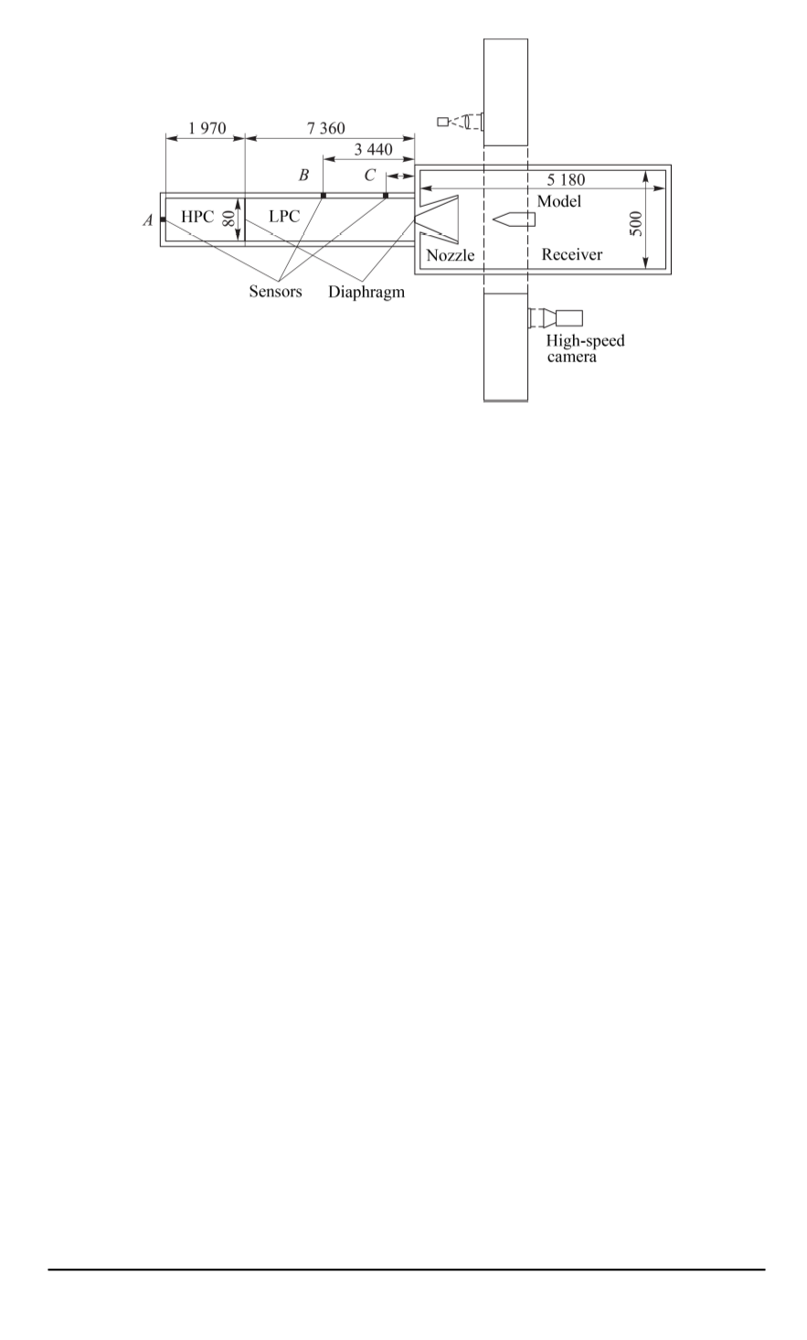

Fig. 1. Schematic view of the testing setup
at the end of the HPC in order to trigger the recording equipment, measure
the shockwave velocity, detect the pressure change and shockwave pattern
history. All sensors are connected to a personal computer via the analog-
digital transducer.
Optical investigation of the flow around the models is conducted
via flat illuminators 260 mm in diameter. Shadow column instruments
(Tepler devices ИАБ-451 were used in this case) provide photo and video
data on the shockwave and boundary layers behavior in the area under
investigation. These data were recorded by means of digital high-speed
video cameras with several thousand shots per second speed. The cameras
were activated by pressure sensors.
The desired rarefaction level in the testing setup segments is achieved
by means of two turbomolecular oil-free vacuum pumps. The high pressure
and low pressure chambers are separated by a copper diaphragm. A system
of blades was used for the uniform and rapid opening of the diaphragm. The
low pressure chamber and the receiver are separated by a thin aluminium
membrane positioned at the nozzle unit entrance.
The shock tube produces Mach 7.0 hypersonic flows in the receiver
segment. A number of experiments were conducted to simulate the flow in
the ramjet air intake. The scaled models have wedge-shaped elements, some
of them blunted. Special cavities on the surface simulate flame holders in
real ramjet ducts [11].
Shock tube experiment results.
Typical readings for pressure sensors
during the experiment are presented in Fig. 2, 3. In this case, the driver
gas is air at 20 bar pressure; the driven gas is air at 100 mbar pressure.
The oscillograph patterns log the pressure changes at 10 cm distance to the
nozzle entrance (sensor
C
, Fig. 1). The first jump (
1
, Fig. 2) indicates the
6 ISSN 0236-3941. HERALD of the BMSTU. Series “Mechanical Engineering”. 2015. No. 1


