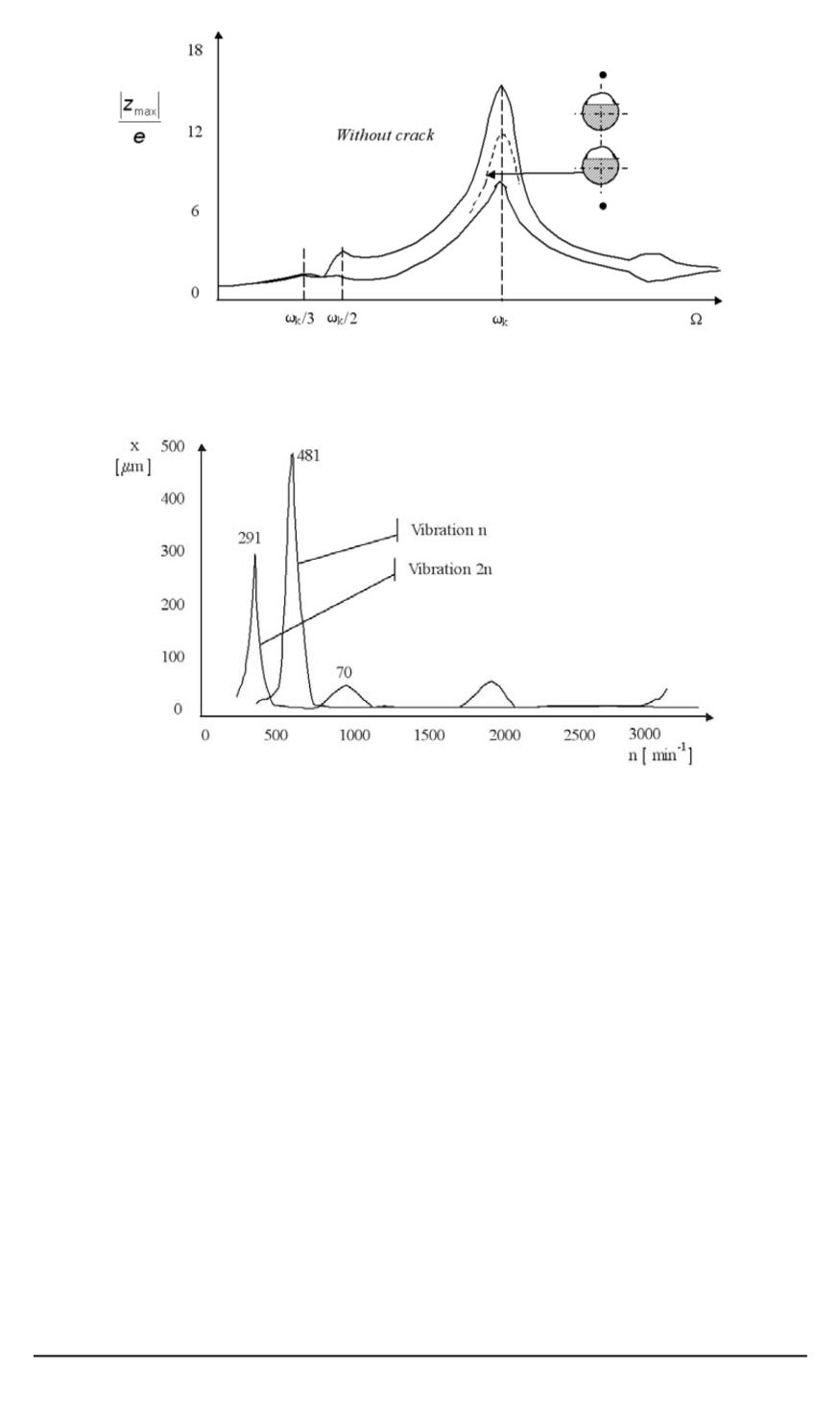
Fig. 6. Maximum vertical amplitude of vibrations as the function of the shaft’s
anglular speed (Laval-shaft with
t
= 0
.
20
r
,
e
= 0
.
030
x
, degree of muffle
D
= 0
.
05
)
Fig. 7. Vibration amplitude
n
and
2
n
in vertical direction, at the induced side of the
generator
At first in corners, then they expanded in the axis direction, and after
that they appeared in the middle of the engine.
The cracks apeared because of fatigue. They appeared first in corners
because of tension high concentration formed since the groove ends for
a length of about 30 mm were fairly roughly worked because of better
isolation attaching. It is apparent that the allowed tension values with the
rotor were exceeded. Those damages were repaired so, that the material
was scraped, and then the cracks disapeared.
To protect at least partial running operation, there needed to be used
the spare rotor. It had then up to 700 working hours. There weren’t any
cracks on it. It was expected to find similar cracks on the rotor like at two
others, after some time. It was decided to be stopped after 45 days due to
security reasons and to be checked. The found condition of the rotor would
be authoritative for the further working periods. Besides that, special steps
used in checking were discovered and this allowed finding cracks and their
spreading without disassembling the rotor. To find out how deep cracks
114 ISSN 0236-3941. Вестник МГТУ им. Н.Э. Баумана. Сер. “Машиностроение”. 2009. № 3


