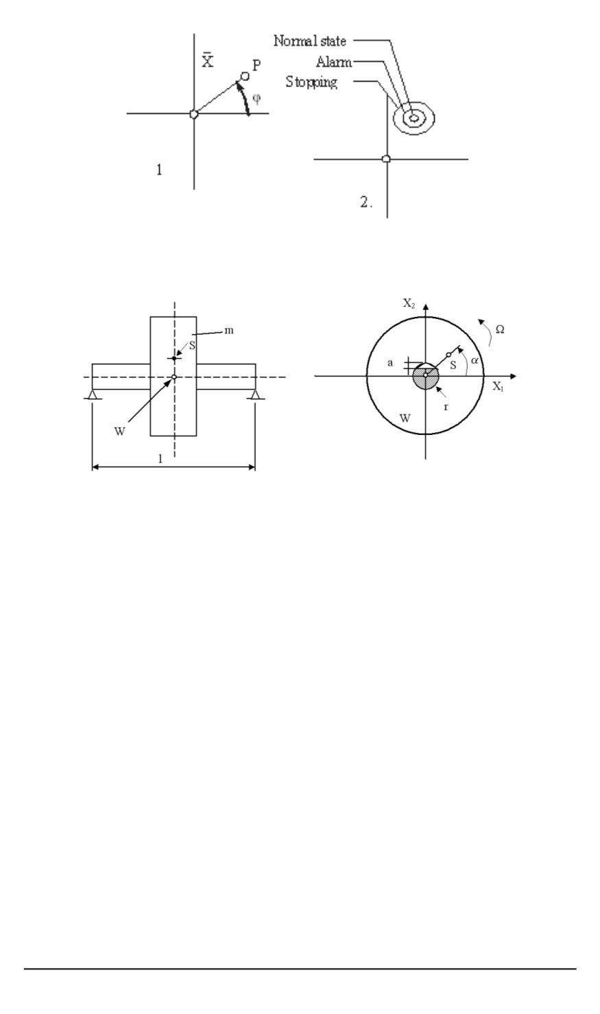
Fig. 3. The polar diagram of the vibration
n
and
2
n
:
1 — the principle sketch; 2 — work areas
Fig. 4. Shaft with crack at
l
/
2
the frequency
Ω
and the radius
y
. Here a vibrations acceptor registers
harmonical motion with the frequency
Ω
and the amplitude
y
. Further the
main moments of inertia are different,
L
2
=
L
1
. At the initial, still small
cracks stiffness reduces only a little, depending on crack growth. So, e.g.
the hardness of the shaft sketched in Fig. 4 at the supposed depth of the
cracks
t
= 0
.
20
r
in the directions 1 and 2 is
k
1
= 0
.
999
k
0
and we can
deduce that the influence of the crack on vibration behavior is still small.
If the surface of the crack is affected by tractive power then the effect of
the crack is maximum because its surface doesn’t endure tractive powers.
In that case it is the crack which “breaths” unlike “open” crack, which
is always like that. The “breathing” of the crack depends on the forces
conditioned by the mass of unbalanceness.
Theory with the time dependant coefficients shows that the shaft’s
center describes circular track, which has similarity with movement
Ω
and partially with
2Ω
and
3Ω
(angular speed
Ω = 2
n
,
n
— number of
revolutions).
For example, in Fig. 5 is shown one flow with the supposition that depth
of the crack and angular speed
Ω =
w
k
3
, where
w
k
stands for the first own
frequency of the shaft without crack.
Shaft’s gravity is for
0
,
030
x
i
, eccentric in direction of the axis
2
α
= 90
◦
.
The middle movement is characterized by the point
P
with coordinates 0
112 ISSN 0236-3941. Вестник МГТУ им. Н.Э. Баумана. Сер. “Машиностроение”. 2009. № 3


