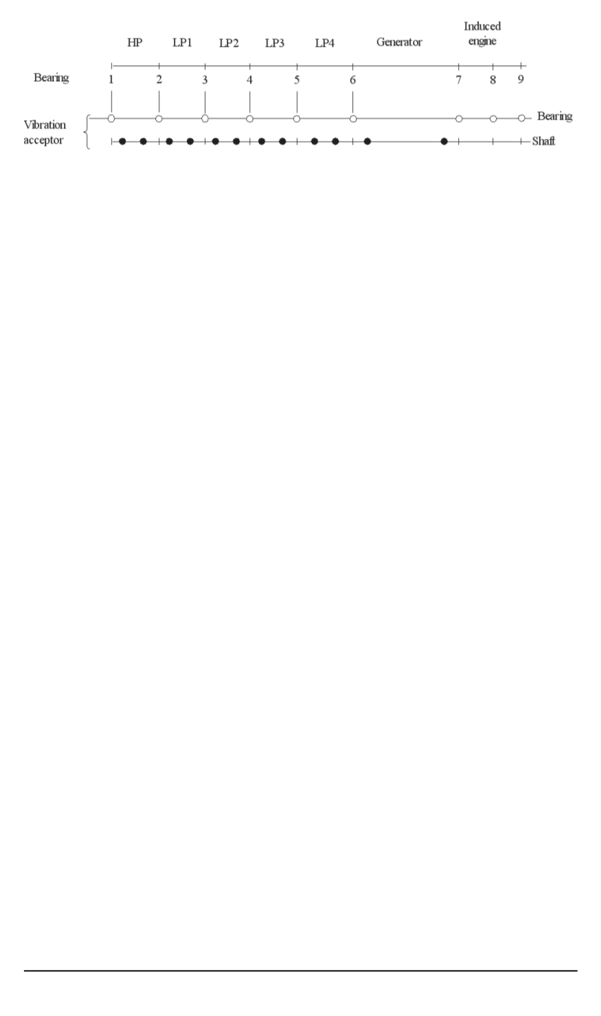
Fig. 2.The additional measuring points for starting (into operation) the bearing
vibrations (horizontally and vertically); the shaft vibrations (horizontally and
vertically) HP — the rotor of high pressure turbine; LP — the rotor of low pressure
turbines
The cracks have been found at the cog ends at the active parts of the
rotor 1 after the operation for 3200 hours and of the rotor 2 after 7600
hours. Since we could expect with great probability that on the new rotor
some cracs would appear, there was applied a vibrations control system in
order to ensure further work. The system has the following characteristics:
— the signals from the measuring points sketched in Fig. 2 can be
registered and processed in computer. Those signals are analysed by
determining amplitude and the phase angle of vibrations
n
and
2
n
;
— the measuring values can be preset on the screen, i.e. registered as the
table of measuring values. The tables contain the effective values as well
the amplitude values of the vibrations
n
and
2
n
at any measuring point. So
received abundance of information comprises the values of 20 vibrations
of bearings and 32 vibrations of shafts (see Fig. 2);
— the amplitude values or phase angles in
xy
-presentation can be
obtained as the function of revolutions number or time;
— the amplitude value and phase angle of vibrations
n
or
2
n
in polar
diagrams are determined with the help of point
P
(Fig. 3). The distance of
the pole is the measure for the
X
amplitude, and the polar angle is identical
to the phase angle
ϕ
, the revolutions number or time are the parameters in
this diagram. The normal state is determined on the ground of the operation
experience and marked with
P
0
. The concentric circles around that point
indicate when there is the state of alarm or when the machine needs to be
stopped (Fig. 4).
The value
Δ
A/
Δ
t
is set as a trend where
Δ
A
=
A
(
t
2
)
−
A
(
t
1
)
and
marks amplitude difference during the time difference
Δ
t
=
t
2
−
t
1
.
For short time and long time trends the differences of 1 hour and 6 days
are chosen.
The vibrations of the rotor with cracks as function of anglular
speed.
Here, we shall use a simple model according to Fig. 4 (Lavall’s
shaft).
The rotor is loaded by its weight
G
and non-balanced force
F
=
m
e
Ω
2
.
If
k
0
is the stiffness of the rotor without a crack, then the weight produces
static bending
x
s
=
G/k
0
. The non-balanced force produces the circular
motion of the shaft middle around the point of its static bending with
ISSN 0236-3941. Вестник МГТУ им. Н.Э. Баумана. Сер. “Машиностроение”. 2009. № 3 111


