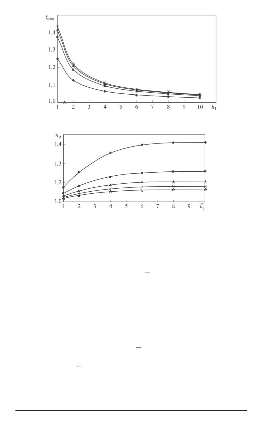

Fig. 4. Dependency of fins end surfaces contribution on finning parameters
ˉ
t
ˉ
t
ˉ
t
:
—
t
= 2
; —
t
= 4
;
N
—
t
= 6
;
×
—
t
= 8
Fig. 5. Dependency of the finning coefficient
η
p
on CC finning parameters with
accounting for the fins end surfaces at Bi = 0.04:
—
t
= 2
; —
t
= 4
;
N
—
t
= 6
;
×
—
t
= 8
;
∗
—
t
= 10
The dependency of
ξ
end
coefficient on finning parameters is shown in
Fig. 4.
With the account for
ξ
end
influence, the finning coefficient
η
f
increases
markedly in the fins low height area (
h
1
= 1
. . .
4
), then it tends to
stable values while increasing simultaneously, with the pitch value growing
(Fig. 5). With the Biot number increasing, the finning coefficient markedly
decreases.
The pattern of change of the combined thermal geometrical parameter
A
∗
=
A
f
η
f
(Fig. 6) has the following implications. As it was expected,
the pattern of
A
∗
change corresponds to the full-size finning with regards
to the fins height, however, its absolute value is 15. . . 30% lower mostly
due to considering only the fins height
h
1
on the heat realing surface while
calculating the finning coefficient. The maximum of its values shifts to the
large-values region
h
1
, which extends the optimal finning parameters zone.
In all other cases, HTI in CC can be calculated and analysed according
to the above presented methodology for the circular finned channels [1]
taking into account their specific factors, parameters and features of coupled
50
ISSN 0236-3941. HERALD of the BMSTU. Series Mechanical Engineering. 2015. No. 2


